

Engineering
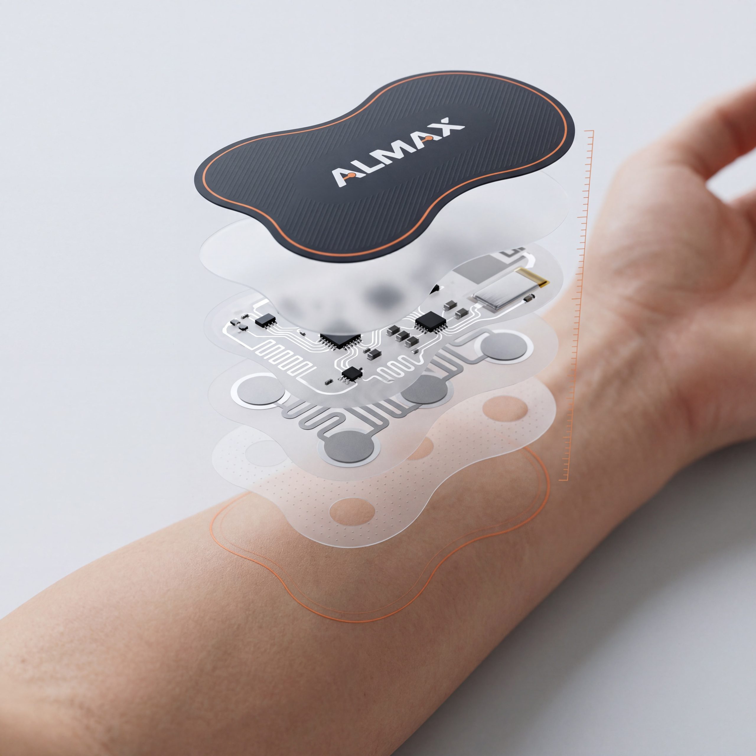
ALMAX engineers custom interfaces and printed electronics end to end — circuit, stack-up, sealing, connector, controller and firmware, test, and documentation. The engineers who release the drawing sit inside the company that owns the factory, so design-for-manufacturing is a conversation, not a rejection letter.
 ISO 9001:2015 · ISO 13485 · IATF 16949 · 100% ALMAX-owned manufacturing
What we engineer
| Discipline | Scope | Typical outputs |
| Electrical | Printed circuit design (silver, carbon, dielectric layers); flex and rigid PCB design; matrix and dedicated-line switch circuits; LED and backlight circuits; capacitive sensor layout; EMI/ESD strategy | Schematic, circuit artwork, pin-out, electrical specification |
| Mechanical | Stack-up engineering; adhesive selection; venting; embossing and tactile geometry; sealing to the enclosure; bezel, housing, and mounting design; tolerance analysis | Stack-up drawing, 3D CAD, 2D dimensioned drawings, tolerance budget |
| Firmware & controls | Capacitive touch controllers and tuning; keypad scanning; LED drive and dimming; host interface over I²C, SPI, UART, RS-485, RS-232, CAN, or USB HID | Controller selection, firmware, host-interface specification, test fixture |
| Interconnect | Tail routing and bend radius; ZIF, crimp, heat-seal, and connectorized terminations; shielded tails | Tail drawing, connector specification, mating-connector callout |
| Test & validation | Force-curve, life, electrical, high-voltage, adhesion, temperature/humidity, and ESD testing; test plan authoring | Test plan, test report, sample data |
| Manufacturing engineering | Design-for-manufacturing review, process selection, tooling definition, first-article review | DFM report, tooling list, production drawing package |
The numbers we design to
The rules of thumb that decide whether a keypad works in the field. Every one is written into the drawing, not left to the factory.
| Decision | Rule | Why |
| Printed silver current | Signal-level only — under 50 mA and 1.5 W per trace | Printed silver is a switch and sensor medium; power routes to copper flex or PCB |
| Silver line and space | 0.30 mm standard · 0.20 mm cleanroom · 0.15 mm in a Class 100 cleanroom (ALMAX capability) | Finer traces cost yield; we specify the loosest that fits |
| Tail bend radius | 6× tail thickness for a set bend · 12× for repeated flex · 24× for dynamic flex | Silver cracks before polyester does |
| Dome force vs. life | Same 6 mm dome: 5 million cycles at 180 g, 10,000 at 300 g (supplier data) | Force is a life budget; SnapMax® holds feel past 5 million actuations typical, 1 million guaranteed |
| Registration | ±0.05 mm conductive · ±0.15 mm graphics · ±0.20 mm lamination | Sets the minimum spacing between a key and its neighbor’s legend |
| Sealing | Name the rated element — a sealed front face is not a sealed assembly | An overlay can be IP-rated to the panel while the tail exit is not; we specify both |
How an ALMAX program runs
- Discovery. Five questions: environment, host electronics and connector, thickness budget, feel, and lighting. If you have a drawing, we start from it; if you have a napkin, we start from that.
- Request for quote. The same engineers who will own the drawing quote the tooling, engineering, and piece price, so the quote already carries the design-for-manufacturing review.
- Purchase order and engineering drawings. Our factory drafts the production drawing package; ALMAX engineering in Carefree, Arizona and Kirkland, Washington reviews it; you approve it. Nothing is tooled before your signature.
- Samples and test. First samples ship within 3 to 5 weeks of your drawing approval, depending on complexity — typically five to you, one or two retained for internal test. Force curves, electrical, and environmental data delivered with the parts. Firmware is bench-tested against your host before the sample ships.
- Production release. First-article review closes the loop between drawing and part; then build-to-order or Rapid Inventory®.
- Change control. Revision-controlled drawings for the life of the program — the standard regulated programs expect, applied to every program.
Design-for-manufacturing: the review that saves the second revision
Most interface programs lose a revision cycle between an outside designer and an outside factory. We remove it. In the DFM review, engineering checks every artwork and drawing against the processes it will meet:
- Cut method. Steel-rule die by default for films up to 0.5 mm; hard tool when tolerance is tighter than ±0.13 mm (.005 in) or volume pays for it; laser for prototypes and runs under roughly 20.
- Stack-up math. Total thickness, adhesive tolerance stack, emboss height versus film thickness, and venting so a sealed key does not pump.
- Dome placement and spacing. Key pitch — 18 to 20 mm center-to-center for gloved industrial use, 12 to 20 mm for handheld — checked against dome diameter and legend spacing.
- Light and dark. LED position versus diffusion route, light-bleed control between keys, deadfront opacity.
- Tail and connector. Exit location, bend radius, mating connector part number, shielding if the host needs it.
- Test coverage. What will be tested at the factory and what data comes with the parts.
Why ALMAX for engineering — with the trade-offs
- Engineering and factory under one owner. The engineer who releases the drawing and the line that builds it answer to the same company. Trade-off: we do not engineer parts for other factories to build; the value is in the pairing.
- One vendor for circuit, mechanics, firmware, and molding. Fewer interfaces to manage — in both senses. Trade-off: for a program that only needs a bare flex circuit built to a finished print, a pure converter may be cheaper; we will tell you.
- Documentation to a regulated standard, by default. Revision-controlled drawings, test reports, and lot traceability on every program — not only the medical and automotive ones.
- Numbers on the table. The rules above are published so you can design with them before you call.
Applications and industries
Medical and laboratory devices (ISO 13485) · Automotive and fleet controls (IATF 16949) · Aerospace & defense · Industrial automation and instrumentation · HVAC and building controls · Wearables and soft-goods electronics. The engineering is the same; the documentation depth and test plan scale to the program.
FAQ’s
Can you engineer to my existing drawing?
Yes. Build-to-print programs start with a DFM review; we return a marked-up drawing with the conflicts and the fixes, then quote.
Do you write firmware?
Yes — for capacitive touch controllers, keypad scanning, LED drive, and the host interface (I²C, SPI, UART, RS-485, RS-232, CAN, USB HID). You own the interface specification; we deliver against it.
Can you help with sealing and an IP rating?
Yes. We specify the sealed element — front face, perimeter gasket, tail exit — and design the venting and adhesive system to reach it. Note: the rating belongs to the assembly in your enclosure, so final IP testing is done at the product level.
What files do you need?
Any of: vector artwork (AI, PDF), mechanical files (DXF, STEP), a schematic or pin-out, and the mating connector part number. Missing pieces are what the discovery call is for.
How long until first samples?
Once you approve the drawings, first samples typically ship within 3 to 5 weeks, depending on complexity — tooled silicone and molded parts sit at the longer end.
Do you sign NDAs?
Yes, before any drawings change hands.